Series 200 Low-Loss Coaxial Cable Type : LMR-200 (DW-200)
Cable Ordering Information
| Part Number | MI Number | NEC / CSA Listing | Remark |
|---|---|---|---|
| DW-200 | TU-1313 | none |
Characteristics
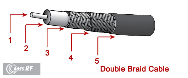
| Material | Detail | inches | mm |
| Inner Conductor | Bare Copper | 0.044 | 1.12 |
| Dielectric | Foamed Polyethylene | 0.116 | 2.95 |
| 1st Outer Conductor | Sealed APA Tape | 0.120 | 3.10 |
| 2nd Outer Conductor | 91% Tinned Copper Braid | 0.142 | 3.60 |
| 3rd Outer Conductor | — | — | — |
| 4th Outer Conductor | — | — | — |
| Floodant | — | — | — |
| Jacket | PE, Black | 0.195 | 4.95 |
| Twisted Pairs | — | — | — |
| Messenger | — | — | — |
| Mechanical Specifications | |||
| Minimum Bend Radius | 0.5 | 12.7 | |
| Product Weight | (less reel) | 21.5 lbs/kft | 32 kg/km |
Customers are reminded that they are SOLELY responsible for confirming that all products are properly installed and used In accordance with all applicable codes and regulations.
uncontrolled copy
All Rights Reserved,
Specifications subject to change without notice
| Electrical Specifications | |||
|---|---|---|---|
| Characteristic Impedance, Ω | 50 ± 3 | ||
| Velocity of Propagation, % | 82 | ||
| Capacitance, Nominal | 24.5 pF/ft | 80.4 pF/m | |
| DC Resistance | Ω / kft | Ω / km | |
| Inner Conductor | 5.36 | 17.59 | |
| Outer Conductor | 4.9 | 16.08 | |
| Loop | 10.26 | 33.67 | |
| Attenuation, Nominal @ 68 °F (20 °C) | ||
|---|---|---|
| Frequency, MHz | dB / 100 ft | dB / 100 m |
| 150 | 4.0 | 13.1 |
| 220 | 4.8 | 15.9 |
| 450 | 7.0 | 22.8 |
| 900 | 9.9 | 32.6 |
| 1500 | 12.9 | 42.4 |
| 1800 | 14.2 | 46.6 |
| 2000 | 15.0 | 49.3 |
| 2500 | 16.9 | 55.4 |
Customers are reminded that they are SOLELY responsible for confirming that all products are properly installed and used In accordance with all applicable codes and regulations.
uncontrolled copy
All Rights Reserved,
Specifications subject to change without notice