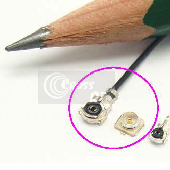
Cross referenced to Hirose U.FL and I-PEX MHF-II series, Cross RF (www.crossrf.com) Miniature Coaxial (MC) RF Connector series features Max mating height 2.5mm and 1.8mm with equivalent or exceed thr electrical features of VSWR 1.35 Max at 7 GHz.
Specially designed to minimize mating space on the circuit boards and mount vertically on RF boards.
Features
- Fully compatible with Hirose U.FL and I-PEX MHF-Ⅱseries
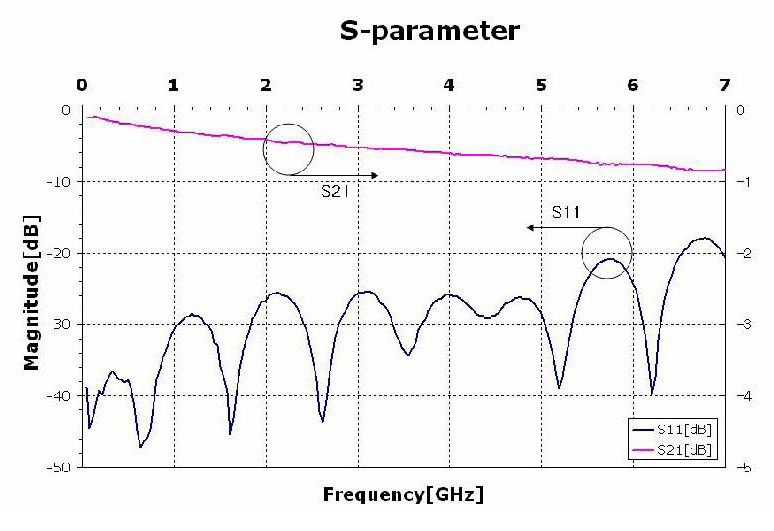
- DC to 7 GHz (VSWR <1.35)
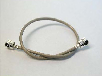
- Cable assembly of 0.70mm, 0.81mm, 1.13mm, 1.30mm and Semi Flexible cables
- Mated heights of 1.80 mm and 2.50 mm
- Vertical mountable on receptacle (SMT)
Applications
- Navigation, DMB, PDA, Notebook PC, GPS, Wireless LAN , Bluetooth
- GSM, GPRS & CDMA mobile Phones
- Measurement instruments and test systems
Mated Height & Dimension
Two connector height options are available:
- U.FLx-LP (Cross Reference to Hirose UFL-LP series) Plug (Max. 2.5mm Mated Height)
- U.FLx-LP(v) (Cross Reference to Hirose UFL-LP(v) series) Plug (Max. 1.8mm Mated Height)
Cable Guide
U.FL-H25 (H 2.5mm Max)
- 070 (Dia : 0.70 mm) – SS&B*
- 081 (Dia : 0.81 mm) – SS&W*
- 113 (Dia : 1.13 mm) – SS&G&B*
- 130 (Dia : 1.30 mm) – SS&G*
- 132 (Dia : 1.32 mm) – DS& G*
- 137 (Dia : 1.37 mm) – SS& B*
U.FL-H18 (H 1.8mm Max)
- 070 (Dia : 0.70 mm) – SS&B*
- 081 (Dia : 0.81 mm) – SS&W*
- 113 (Dia : 1.13 mm) – SS&G&B*
* (SS : Single Shield, DS : Double Shield, B : Black color, W : White color)
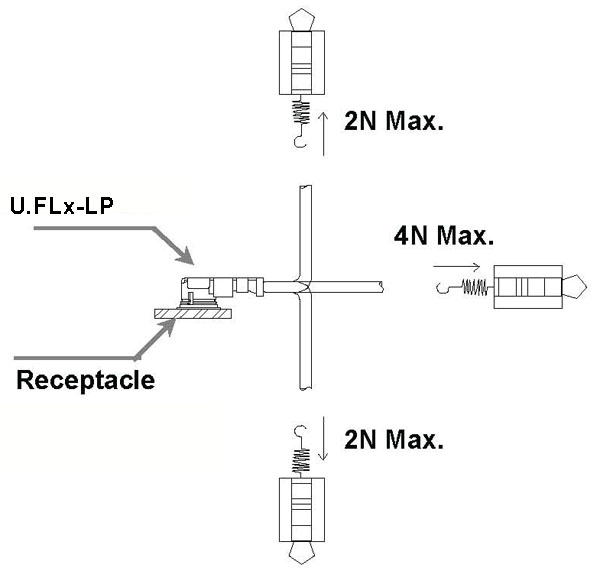
Usage Precautions
Specifications
| Item | Specifications | Conditions |
|---|---|---|
| Impedance | 50 ohm ± 1 | TDR Measurement |
| Insulation Resistance | 500 M Ohms min. | 100V DC |
| 070 (Dia : 0.70 mm) SS, U.FLx-LP-H25 on both ends | 1.35 Max. up to 7 GHz | |
| 081 (Dia : 0.81 mm) SS, U.FLx-LP-H25 on both ends | ||
| 113 (Dia : 1.13 mm) SS, U.FLx-LP-H25 on both ends | ||
| 130 (Dia : 1.30 mm) SS, U.FLx-LP-H25 on both ends | ||
| VSWR | 132 (Dia : 1.32 mm) DS, U.FLx-LP-H25 on both ends | |
| 137 (Dia : 1.37 mm) SS&, U.FLx-LP-H25 on both ends | ||
| 070 (Dia : 0.70 mm) SS, U.FLx-LP-H18 on both ends | ||
| 081 (Dia : 0.81 mm) SS, U.FLx-LP-H18 on both ends | ||
| 113 (Dia : 1.13 mm) SS, U.FLx-LP-H18 on both ends | ||
| Unmating Force | 0.2 N min. | Measured by a 0.5mm pin gauge |
| Durability | Contact Resistance Center : 20 m Ohms max. Outside : 10 m Ohms max. | 30 cycle |
| Humidity (Steady State) | No damage, cracks or parts dislocation. Insulation resistance 100M Ohms min. (when high humidity) Insulation resistance 500M Ohms min. (when dry) | 96 hours at temperature of 40 ℃ and humidity of 95% |
Material & Finish
| Parts | Components | Materials | Finish |
|---|---|---|---|
| shell | phosphor bronze | silver plated | |
| Plug | insulator | PBT | black color |
| center contact | phosphor bronze | gold plated | |
| shell | phosphor bronze | silver plated | |
| Receptacle | insulator | LCP | beige color |
| center contact | brass | gold plated |


